Fretting corrosion is a deceptively small-motion failure that can disable a large machine. It develops where two contacting surfaces experience repeated oscillation, vibration, or micro-slip rather than full sliding. The contact may move only a few micrometers, yet the damage can loosen a bearing fit, scar a shaft, or initiate a fatigue crack. In my consulting work, I most often see it at bearing seats, bolted joints, splines, couplings, and electrical connectors exposed to vibration.
The key engineering mistake is treating this as ordinary rust or as a lubrication problem alone. The damage requires a contact load, relative movement, and an environment that allows oxide debris to accumulate. In the lab we call this an oscillating-contact wear process; on your shop floor, it means a component can look properly assembled and still be losing material every hour.
What Causes Fretting Corrosion?
Fretting starts when two loaded surfaces repeatedly move against each other over a very short distance. Vibration from an electric motor, gear mesh, reciprocating compressor, marine engine, or wind turbine can provide the motion. Thermal expansion can do the same thing in a tightly fitted assembly. The contact pressure is high, but the sliding distance is too small to sweep debris away.
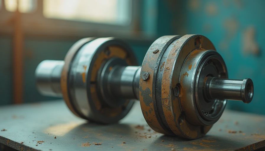
At first, asperities—small peaks on otherwise smooth metal surfaces—adhere and break apart. Fresh metal is exposed to air, and oxidation produces fine reddish-brown or black debris. That debris is abrasive. It can remain trapped in the contact, increasing wear and changing the fit. The resulting rust-colored powder is often called fretting debris, although its color depends on the alloy, temperature, humidity, and lubricant.
Three failure modes, one root cause: adhesive junctions break, oxide particles abrade the surfaces, and fatigue develops beneath the damaged zone. A shaft seat can lose material and create a loose fit. A spline can develop backlash. A bolted flange can lose preload as the contact surfaces settle. The visible corrosion is therefore only part of the problem.

A useful distinction is between fretting wear and fretting corrosion. Fretting wear emphasizes mechanical material removal. Fretting corrosion emphasizes oxidation and chemical interaction with the environment. Real equipment commonly experiences both. ISO 15243 identifies fretting corrosion as a recognizable damage pattern in rolling bearings, while ASTM G40 provides terminology for describing wear, erosion, and related surface processes. These references help maintenance teams use consistent language during inspection.
Where Fretting Corrosion Appears First
Rolling-element bearing fits are a classic location. A bearing ring that should be stationary can microslip on a shaft or in a housing when vibration, load reversals, or an incorrect fit is present. The marks may appear as dark bands around the shaft seat or housing bore. If left in service, the damaged area can reduce interference and allow more movement, creating a self-reinforcing failure.
Splined shafts and shrink-fit couplings face a similar risk. A torque reversal or fluctuating load can produce small relative movements at the tooth flanks. On a high-speed gearbox, this can create polished patches, red oxide, and eventual tooth profile loss. Electrical connectors and grounding interfaces are also vulnerable because oxide films increase electrical resistance while vibration continues to disturb the contact.
Bolted joints deserve special attention. A joint does not need to separate visibly to experience micro-slip. If the applied transverse load exceeds the friction available from bolt preload, the faying surfaces can move slightly during every vibration cycle. The joint may then lose preload, loosen, or develop fatigue cracks at stress concentrations.
Application Note: For a motor connected to a pump, inspect the motor bearing fits, coupling hub, keyway, and foundation bolts together. Finding oxide at one location should prompt a vibration and preload review elsewhere, not just a cleaning operation.
How to Diagnose the Damage
Begin with evidence, not assumptions. Record the location, load direction, operating temperature, vibration history, assembly torque, shaft or bore dimensions, and lubricant used. Photograph the contact before cleaning. A reddish powder at a bearing seat is suggestive, but it is not proof; ordinary corrosion, assembly damage, and false brinelling can produce overlapping appearances.
Use a calibrated micrometer, bore gauge, or coordinate measuring machine to quantify material loss. Check for circumferential ridges, axial bands, polished high spots, and a change in interference fit. For bearings, compare the damaged zone with the load direction and inspect raceways for false brinelling. False brinelling produces indent-like marks from vibration while the bearing is stationary or slowly oscillating; it can coexist with fretting corrosion but is not identical to it.
Vibration data can expose the cause. A portable accelerometer or route-based condition-monitoring system may show a change after the fit becomes loose. Review spectra for increased harmonics, looseness indicators, and changes at running speed. For critical parts, dye penetrant or magnetic particle testing can identify cracks after debris removal, provided the method is suitable for the material and surface condition.
Lubrication and Design Controls
Lubrication can reduce direct metal contact, exclude moisture, and carry away some debris, but grease is not a cure for an unstable fit. Select the product for the contact and environment. For grease, identify consistency by NLGI grade under ASTM D4950 or the relevant product specification; an NLGI 2 grease is common for many general bearing applications, but grade alone does not establish fretting protection. Additive chemistry, base oil viscosity, compatibility, and water resistance matter.
Anti-fretting pastes often use solid lubricants such as molybdenum disulfide or graphite, but these products must be compatible with the joint, temperature, electrical requirements, and assembly procedure. Do not apply a conductive or electrically insulating product to a connector without confirming the design requirement. On precision fits, excessive compound can alter dimensions and assembly force.
The stronger controls are mechanical. Use the specified interference or transition fit, verify shaft and bore tolerances, and control surface finish. Improve joint preload where the design permits, increase contact area, reduce vibration, and eliminate misalignment. A coupling guard that prevents contamination does not correct a loose hub. Likewise, replacing grease without correcting a bearing fit often produces only a short delay.
A Practical Maintenance Procedure
When inspection confirms fretting corrosion, isolate the machine and document the condition before dismantling. Clean the parts with a compatible solvent and lint-free materials; avoid abrasive polishing that removes evidence or changes the fit. Measure the shaft, bore, spline, or contact face at several positions. Compare the results with the equipment drawing, manufacturer limits, and the applicable bearing or coupling specification.
If damage is superficial and dimensions remain within tolerance, controlled cleaning, approved assembly compound, corrected preload, and vibration verification may be sufficient. If the fit is loose, the repair may require a new shaft, sleeve, housing repair, or engineered retaining solution. Do not rely on threadlocker or a heavier grease as a substitute for restoring the load path.
After reassembly, capture baseline vibration and temperature readings. Recheck the joint after initial operation and again at the next planned inspection. The goal is not merely removing red powder; it is demonstrating that relative motion has been reduced and the contact remains dimensionally stable.
Fretting corrosion is best controlled before the first visible stain. Treat vibration, fit, preload, moisture, and lubricant as one tribological system. By the relevant standard and the actual machine drawing, define what acceptable contact, surface condition, and lubricant application mean. That discipline turns a mysterious reddish mark into a diagnosable and preventable reliability problem.





No feedback yet — submit the first.