When an engine develops oil leaks, sludge, unstable idle, or unexplained oil consumption, technicians often look first at seals and piston rings. The more fundamental question is whether positive crankcase ventilation is controlling pressure and contamination correctly. This system is small, inexpensive, and chemically important: it removes combustion gases from the crankcase before those gases degrade lubricant, corrode surfaces, or force oil past a gasket.
I approach the subject as a tribologist rather than treating the valve as a disposable emissions part. The crankcase is a working chemical environment. Blow-by carries water vapor, unburned fuel, carbon particles, and acidic combustion products into the oil mist above the sump. If that mixture remains trapped, the lubricant has to neutralize contaminants while maintaining a protective film on bearings, cam lobes, and cylinder walls.
What positive crankcase ventilation actually does
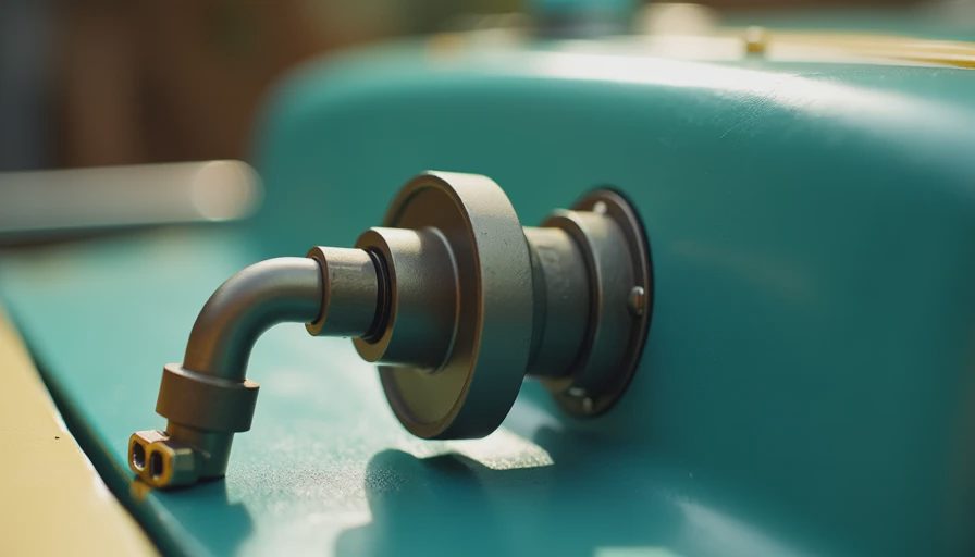
Positive crankcase ventilation routes crankcase vapors back into the intake system, where the engine burns them. Older engines sometimes relied on a simple road-draft tube, but modern systems use controlled vacuum, hoses, baffles, and a metering valve. The valve limits flow during high intake vacuum and allows greater vapor movement under load, when blow-by production normally increases.
The word positive matters. Natural pressure differences alone are not the complete control strategy. A functioning system continuously sweeps the crankcase, maintaining slight vacuum or at least preventing harmful pressure buildup. The exact arrangement varies among gasoline, diesel, turbocharged, and hybrid engines, but the engineering objective remains the same: remove vapor without pulling excessive liquid oil into the intake.
In the lab we call this contaminant transport control. On your shop floor, it means fewer deposits and less pressure trying to push oil through the weakest seal. The system does not eliminate blow-by. It manages the consequences.
A typical failure is a stuck valve. If it remains closed, crankcase pressure rises. If it remains open, intake vacuum can draw too much oil mist through the system, causing blue exhaust smoke, elevated oil consumption, or deposits near the throttle body. A split hose can create an unmetered air leak and produce similar drivability symptoms.
Why the system matters to lubricant life
Combustion gases change oil chemistry even when the dipstick level looks normal. Water can promote rust and additive depletion. Fuel dilution lowers viscosity and weakens the hydrodynamic film that separates loaded surfaces. Soot and oxidation products increase sludge and varnish formation. Acidic species consume alkaline reserve in engine oil, commonly represented by total base number, or TBN.
This is where positive crankcase ventilation intersects directly with tribology. A bearing does not fail because a valve is labeled an emissions component; it fails when contamination, viscosity loss, starvation, or surface loading reduces the oil film below a safe margin. The valve is one part of the contamination-control chain.
Oil selection still matters. Use the viscosity and performance category specified by the vehicle manufacturer, such as an applicable API gasoline or diesel category, rather than assuming a thicker oil will compensate for poor ventilation. For a fleet, trend oil condition with a consistent sampling method. ASTM D445 covers kinematic viscosity, ASTM D5185 is commonly used for elemental analysis by ICP, and ASTM D6304 addresses water by Karl Fischer titration. These tests help distinguish a ventilation problem from coolant ingress, fuel dilution, or abnormal wear.
An oil sample showing rising iron, silicon, fuel, or water deserves investigation rather than an automatic oil change. The ventilation path, air filtration, injector condition, compression, and operating duty should be considered together.
Three practical failure modes and their clues
The first failure mode is restricted flow. Look for crankcase pressure, oil seepage around seals, a dipstick that is pushed upward, and sludge in the valve or hose. A quick check with a suitable pressure gauge is more informative than simply shaking a removable valve. Follow the service information for the engine because allowable crankcase pressure differs by design.
The second is excessive flow. A whistling noise, lean idle fault, rough running, or oil in the intake tract can indicate an uncontrolled vacuum path. Turbocharged engines deserve special attention because compressor inlet routing, boost pressure, and check valves must work in the intended direction. Replacing only the valve while ignoring a hardened hose often produces a temporary repair.
The third is frozen or contaminated hardware. Short trips encourage water and emulsion formation, especially in cold climates. A vehicle that idles frequently or operates below full temperature has a different contamination load from one that runs two hours at highway speed. In Seattle winters, I pay close attention to moisture in the hose and cover passages; in dusty industrial service, I also inspect the upstream air filtration and breather architecture.
Application Note: For a generator or auxiliary engine that runs long periods at light load, record oil level, exhaust appearance, crankcase pressure, and operating temperature together. A clean-looking dipstick does not prove that vapor removal is adequate.

A disciplined inspection procedure
Begin with the engine off and cool enough for safe handling. Confirm the oil level and note whether the oil smells strongly of fuel or appears milky. Inspect every hose for collapse, soft spots, oil saturation, and loose connections. Remove the valve or separator only according to the manufacturer’s procedure; some modern engines integrate the regulator into a valve cover or oil-separator assembly.
Next, check for intake leaks and verify that one-way check valves are oriented correctly. Scan for diagnostic trouble codes, but do not let a code replace mechanical inspection. A lean code can result from a ventilation leak, while an oil-consumption complaint can originate in piston rings, turbo seals, valve guides, or an overfilled sump.
After repair, clean accessible oil residue and establish a baseline. Recheck idle quality, intake deposits, crankcase pressure, and oil level after a meaningful operating interval. For fleet equipment, document the part number, engine hours, oil specification, and symptom before and after service. That record prevents repeated parts replacement without diagnosis.
Protect the system with the right maintenance plan
Positive crankcase ventilation is not a universal interval item with one replacement schedule. Inspection frequency should follow duty cycle, engine design, and contamination history. Passenger vehicles used for short trips need more attention to moisture and deposits. High-mileage engines may need separator cleaning or diaphragm inspection. Diesel and turbocharged equipment can require additional checks for oil carryover and hose integrity.
Do not install an unrestricted breather as a shortcut. It can alter emissions behavior, contaminate the engine compartment, and remove the controlled pressure balance the engine was designed to use. Do not select oil solely by viscosity, either. Follow the owner’s manual or fleet specification, including the required API category and manufacturer approvals.
The value is measurable in avoided work: fewer nuisance leaks, cleaner intake hardware, more stable lubricant condition, and earlier detection of ring or injector problems. A replacement valve may cost roughly $20 to $100 on a common passenger vehicle, while a neglected pressure problem can contribute to repairs costing hundreds or thousands of dollars. Parts prices vary, but the diagnostic logic does not.
The shop-floor conclusion
Positive crankcase ventilation is a pressure-control and contaminant-management system, not merely an emissions accessory. It protects the oil environment that supports bearings, rings, camshafts, and turbocharger components. When symptoms appear, test the complete path: valve, hoses, separator, check valves, intake connection, and engine condition.
In the lab we call this controlling the crankcase atmosphere. On your shop floor, it means keeping contaminants moving out before they become an oil-film problem. Inspect the system during routine service, use the specified lubricant, and confirm the repair with pressure, leak, and oil-condition evidence rather than guesswork.





No feedback yet — submit the first.