Hydraulic pressure is not simply a number shown on a gauge. It is the response of a fluid power system to resistance, flow demand, leakage, temperature, and component condition. When pressure falls, climbs unexpectedly, or fluctuates, the failure may begin in a pump, relief valve, filter, actuator, or contaminated oil. The practical objective is to identify where energy is being lost before a minor fault damages an expensive machine.
What hydraulic pressure actually tells you
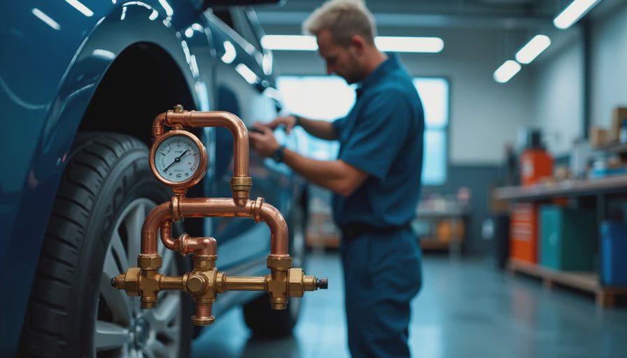
A pump creates flow; resistance to that flow creates hydraulic pressure. This distinction is fundamental. A positive-displacement pump can move oil through a low-resistance circuit with modest pressure, but pressure rises when a cylinder meets a load or a valve restricts passage. The gauge therefore reports the force required to maintain flow against resistance, not the health of the pump by itself.
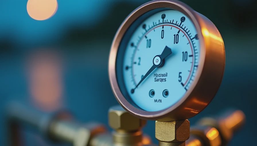
Pressure is commonly expressed in pounds per square inch, or psi, in U.S. plants. Pascal and bar units are also common in engineering documentation. One bar is approximately 14.5 psi. Always compare a measurement with the machine manufacturer’s specification at a defined oil temperature, engine speed, and load. A reading taken during cold startup cannot be compared directly with a reading from a warmed system under production load.
In the lab we call this a pressure-flow relationship; on your shop floor, it means a gauge reading only becomes useful when you know the operating conditions behind it. A 3,000 psi rating on a hose, for example, does not mean the circuit should operate continuously at that value. Working pressure, transient pressure, and proof pressure are different specifications.
Three failure modes, one root cause
Low hydraulic pressure usually points toward insufficient pump output, an incorrectly adjusted relief valve, internal leakage, or a restriction on the pump inlet. A worn pump may still produce acceptable pressure at no load while failing to maintain flow when an actuator is working. That is why a deadhead test, if permitted by the equipment manufacturer, must be brief and performed with a calibrated test gauge.
Excessive hydraulic pressure can result from a blocked return path, a stuck directional valve, an incorrectly set relief valve, or an actuator that cannot move. The consequence is more than a high gauge reading. Seals can extrude, hoses can burst, and oil temperature can increase rapidly as energy becomes heat. Never loosen a fitting to “bleed” pressure from a live circuit. Lock out the machine and verify zero stored energy first.
Pulsation deserves separate attention. Rapid needle movement can come from pump cavitation, air entrainment, a damaged coupling, a failing accumulator, or a relief valve chattering near its setting. Recording the frequency and operating condition of the fluctuation often separates a mechanical problem from a control problem.
Oil condition and pressure loss
Hydraulic oil does not wear out in the same way a bearing does, but it can oxidize, aerate, emulsify with water, and carry abrasive particles. Each condition changes how the system behaves. Oxidized oil can form varnish that restricts spool movement. Water can reduce lubricating film strength and promote corrosion. Air makes the fluid compressible, producing spongy actuator movement and unstable hydraulic pressure.
For cleanliness, use the machine builder’s target ISO 4406 code rather than choosing an arbitrary filter rating. ISO 4406 reports particle counts at three size ranges, allowing a maintenance team to compare samples consistently. Filter selection should also consider beta ratio, dirt-holding capacity, flow rate, and the pressure drop at operating temperature. A very fine filter that is undersized can create bypass flow or starve the pump.
Application Note: On a paper-mill hydraulic power unit, a rising differential-pressure indicator across the return filter is not merely a filter-service reminder. It can indicate varnish, fiber contamination, cold oil, or a return flow increase caused by internal leakage. Sample the oil and inspect the filter debris before replacing elements repeatedly.
A disciplined test sequence
Start with the simplest observations. Check reservoir level, oil appearance, visible leaks, hose condition, filter indicators, and unusual noise. Confirm that the correct fluid is installed and that the breather is open and clean. A blocked breather can create a vacuum in the reservoir, restricting pump inlet flow and causing cavitation.
Next, install a calibrated gauge at the test port closest to the component being evaluated. Compare standby pressure, operating pressure, and relief pressure with the service manual. If possible, measure flow with a flow meter at the same time. Pressure without flow data can hide internal leakage: a pump may reach relief pressure while delivering too little useful flow to move a cylinder at the required speed.
Measure temperature as well. Most hydraulic oil is specified around a normal operating range, often near 100 to 140 degrees Fahrenheit, but the correct limit depends on the fluid, seals, and machine. Excessive heat lowers viscosity and increases leakage across clearances. In tribology terms, the lubricating film becomes less robust; in maintenance terms, the machine loses efficiency and the oil ages faster.
Choosing fluid and components by specification
Use the fluid grade and performance category stated by the equipment manufacturer. ISO viscosity grades such as ISO VG 32, 46, and 68 describe kinematic viscosity at 40 degrees Celsius; they do not identify every additive or performance property. An anti-wear hydraulic fluid meeting a stated manufacturer requirement is not automatically interchangeable with every biodegradable, fire-resistant, or automotive fluid.
Hoses, fittings, seals, and valves must be selected for compatible pressure, temperature, and chemical exposure. A hose should have a suitable working-pressure rating with allowance for pressure spikes and mechanical movement. SAE standards are commonly used for hydraulic hose and fitting requirements, while ISO documentation is often used for cleanliness and fluid-power terminology. The exact standard listed by the machine builder should control the purchase.
When grease is used on nearby pins or bearings, select it by application and consistency, not color. NLGI grades describe grease consistency, while base oil viscosity, thickener type, water resistance, and load performance determine suitability. A grease problem can create actuator friction that looks like a hydraulic pressure problem, so inspect the complete force path.
Turning readings into a maintenance decision
Create a baseline after a successful repair. Record oil temperature, pump speed, standby pressure, loaded pressure, actuator time, filter differential pressure, and ambient conditions. Repeat the same measurements during scheduled inspections. A gradual increase in relief pressure accompanied by slower actuator movement suggests rising internal leakage or restriction; a sudden change points more strongly toward a failed valve, hose, coupling, or control component.
Oil analysis adds evidence before disassembly. Ask the laboratory for viscosity, particle count to ISO 4406, water content, oxidation indicators, and wear metals when appropriate. ASTM methods are commonly used for viscosity and water testing, but the laboratory report should identify the method used. Trend results rather than reacting to a single number without operating context.
A reliable troubleshooting program connects gauge data with fluid condition and component inspection. That approach reduces unnecessary pump replacements, prevents repeated filter changes, and catches heat-related damage early. If a system is unstable, isolate stored energy, verify the measurement with a known-good gauge, and follow the manufacturer’s pressure limits. Good hydraulic reliability begins with disciplined observation, not a higher relief-valve setting.



No feedback yet — submit the first.