A worm and worm wheel gear set converts rotary motion through a screw-like worm engaging a toothed wheel. It is compact, quiet, and capable of high reduction in one stage, but that convenience creates a difficult lubrication problem. Sliding dominates the contact, heat can accumulate quickly, and an incorrect oil can damage the wheel or waste power. In a worm and worm wheel gear assembly, the right service decision begins with contact geometry, speed, load, and temperature rather than with viscosity alone.
How the gear set transmits load
The worm resembles a helical screw, while the worm wheel is usually a bronze or bronze-alloy gear shaped to wrap around it. As the worm rotates, its threads slide across the wheel teeth. The speed ratio depends mainly on the number of worm starts and the number of wheel teeth. A single-start worm driving a 40-tooth wheel provides an approximate 40:1 ratio, although efficiency and backdriving behavior depend on the helix angle, friction, and load.
This sliding contact distinguishes the arrangement from a typical spur or helical gearbox. Rolling is limited, so the oil film must tolerate substantial shear and heat. In the lab we call this mixed or boundary lubrication when surfaces partly approach contact; on your shop floor, it means polished tooth flanks, rising sump temperature, and eventual scoring if the film collapses.
The wheel material deserves equal attention. Steel-on-steel lubricant chemistry that performs well in another gearbox can stain, soften, or aggressively attack copper-containing alloys. Sulfur-phosphorus extreme-pressure additives are a classic example: some formulations are suitable for steel gears but unsuitable for bronze worm wheels. Always use the equipment manufacturer’s compatibility statement and lubricant data sheet before changing products.
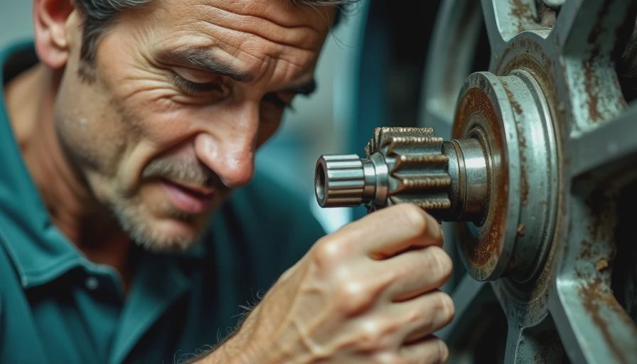
Selecting lubricant viscosity and chemistry
For a worm and worm wheel gear, viscosity is normally selected from the reducer manufacturer’s speed, load, and operating-temperature guidance. ISO viscosity grades such as ISO VG 220, 320, 460, or 680 describe kinematic viscosity at 40 degrees C; they do not, by themselves, prove that an oil is safe for bronze. A high grade can reduce wear under heavy loading, yet it can also increase churning losses and starting torque in a cold plant.
A practical selection process has four steps. First, identify the wheel alloy and confirm whether the reducer requires a mineral oil, a polyalphaolefin synthetic, or another formulation. Second, record input speed, ambient temperature, and duty cycle. Third, compare the candidate oil’s viscosity-temperature behavior and copper corrosion results. ASTM D130 is commonly used for copper-strip corrosion testing, although a passing result should not replace a specific manufacturer approval. Fourth, confirm seal compatibility, especially when switching from mineral oil to synthetic chemistry.
Many industrial products are sold specifically as worm gear oils because their additive packages are designed for sliding contacts and yellow-metal compatibility. That label is useful, but it is not a substitute for reading the technical data sheet. NLGI grades apply to greases, not gear oils. If the housing is grease-filled, the manufacturer should specify the NLGI grade and thickener type; do not assume that an NLGI 2 multipurpose grease belongs in a high-speed worm reducer.
Why temperature is the first warning signal
Worm drives commonly operate warmer than comparable rolling-contact gearboxes because sliding friction converts more mechanical energy into heat. Measure housing temperature at a repeatable location with an infrared instrument or contact probe, and record ambient temperature, load, and speed with every reading. A single number is less useful than a trend. A gradual increase over several weeks can reveal oil oxidation, overloading, bearing damage, or a blocked cooling surface.
Oil level also matters. Too little oil starves the mesh and bearings; too much oil can create churning and raise temperature. Use the specified static level, with the reducer stopped and positioned correctly. Foaming, darkened oil, metallic particles, or a sharp burnt odor justify investigation rather than simply topping up.
Application Note: On a conveyor drive operating continuously in a warm packaging area, compare the temperature after startup and after several hours at production load. If the temperature climbs steadily while motor current remains normal, inspect oil condition, level, breather cleanliness, and wheel-to-worm alignment before increasing viscosity.
Three failure modes, one root cause
The first common failure mode is abrasive wear. Dirt, rust, or hard particles enter through a damaged seal or dirty breather and scratch the tooth surfaces. The second is adhesive wear, often called scoring or scuffing, when the protective film fails under load and local metal transfer begins. The third is pitting or fatigue damage, which appears as small cavities caused by repeated stress. These mechanisms can overlap, and contamination often accelerates all three.
A worm and worm wheel gear may also fail through wheel tooth deformation. Bronze is selected for its favorable sliding behavior against steel, but it is not immune to overload or thermal damage. Look for smeared tooth surfaces, a widened contact band, unusual backlash, and bronze-colored debris in the oil. Bearing failures can misalign the mesh and produce symptoms that initially look like lubrication failure.
Do not diagnose by color alone. Dark oil can reflect oxidation, additive reaction, or contamination, while clean-looking oil can have lost viscosity or contain fine particles. A used-oil sample sent for viscosity, elemental analysis, particle count, and water testing provides a better decision basis. ASTM methods are widely used by laboratories, but trend comparison against the same gearbox is often more valuable than a universal alarm limit.
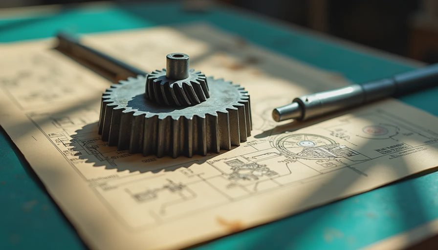
Inspection and oil-change procedure
Begin with a safe shutdown, lockout, and adequate cooling period. Clean the filler, drain, and inspection areas before opening the housing so external grit cannot fall inside. Note the lubricant brand, product grade, operating hours, temperature, and approximate drained volume. Examine the magnetic drain plug if fitted, and retain a sample from the flowing oil rather than from the bottom sludge.
Inspect seals, breathers, mounting bolts, and the visible tooth contact pattern. A breather clogged with dust can create pressure that pushes oil past seals. Refill through a clean, dedicated transfer container and stop at the specified level. Mixing products is poor practice unless the suppliers confirm compatibility; drain and flush when changing chemistry or when contamination is suspected.
For a worm and worm wheel gear in seasonal service, inspect before startup after long storage. Condensation can introduce water, while an idle wheel may develop a static contact pattern. Rotate the machinery by hand where safe, verify free movement, and check that the oil has not separated or emulsified. Record findings in the maintenance system so the next technician can see whether wear is stable or accelerating.
Improving reliability without overengineering
Alignment and mounting are lubrication controls, not merely mechanical details. A soft foot, distorted base, loose coupling, or excessive shaft deflection can concentrate load on one edge of the wheel. Correcting the foundation may reduce temperature more effectively than changing oil. Confirm shaft alignment according to the reducer and coupling manufacturer’s procedure, then verify backlash and contact pattern where inspection access permits.
Use ISO 20816 guidance when evaluating vibration severity for applicable rotating machinery, but interpret the result with the gearbox design and manufacturer limits. Vibration, temperature, oil analysis, and noise should be reviewed together. A new rumble accompanied by rising temperature and ferrous debris is a stronger warning than any one measurement alone.
The best maintenance program is usually simple: scheduled visual checks, documented temperature trends, clean oil handling, periodic sampling, and a defined response to contamination or heat. For a worm and worm wheel gear, those basics protect the bronze wheel, preserve efficiency, and prevent a low-cost lubricant mistake from becoming a production-stopping rebuild. When the data points toward a problem, investigate the mesh, bearings, seals, load, and chemistry as one system.





No feedback yet — submit the first.