A lip seal is a small component with an expensive job: keeping lubricant inside a machine while excluding water, dust, and process contamination. When it fails, the visible oil drip is usually the final symptom, not the original cause. Shaft wear, incorrect interference, heat, chemical attack, or poor installation may have been damaging the sealing interface for weeks. In the lab we call this a controlled elastohydrodynamic contact; on your shop floor, it means a carefully managed oil film separates the sealing edge from the rotating shaft.
How a Lip Seal Actually Works
A typical rotary lip seal uses an elastomeric sealing element, a garter spring, and a rigid outer case. The sealing lip presses against the shaft with radial force. During rotation, microscopic surface texture on the shaft drags a very thin lubricant film beneath the lip. That film reduces friction and heat while the pressure gradient across the contact prevents bulk leakage.
The goal is not a dry interface. A completely dry lip seal runs hot, hardens, and wears rapidly. Excessive oil, however, does not automatically cause leakage; the important variables are viscosity, shaft speed, pressure, and the seal's ability to maintain a stable meniscus. Pressure-rated designs often use a secondary pressure lip or a geometry different from a conventional low-pressure dust seal.
Material selection is equally important. Nitrile rubber, commonly identified as NBR, is widely used with mineral oils and moderate temperatures. Fluorocarbon elastomer, often called FKM or by the trade name Viton, offers better resistance to heat and many aggressive fluids. PTFE designs tolerate demanding temperatures and low-friction applications but require more disciplined installation. A material that works well in a gearbox can swell or lose elasticity in a system using a different synthetic fluid.
Shaft Finish, Hardness, and Lubrication
Many seal replacements fail because the new part is installed on the same damaged shaft. A visible groove at the old contact track changes the local geometry, reducing lip contact and creating a leak path. Measure the shaft with a micrometer rather than judging it by touch. If the groove is deep, a repair sleeve, shaft replacement, or a deliberate change in seal position may be more reliable than installing a second seal in the original track.
Surface finish must be smooth enough to avoid abrasive wear but not so polished that it cannot retain a useful lubricant film. The seal supplier's specification should control the final value; many rotary applications fall in a fine-ground range around 0.2 to 0.8 micrometers Ra, but that is not a universal prescription. Helical machining marks are especially dangerous because they can act like a tiny screw pump and move oil past the lip.
Shaft hardness matters when contamination or high cycle counts are expected. A soft steel journal can develop a wear track quickly, particularly in a dirty hydraulic or marine environment. Filtration and cleanliness should be addressed with the seal. ISO 4406 is the useful reference for reporting hydraulic-fluid particle contamination. It does not select the seal, but it gives the maintenance team a common language for deciding whether abrasive particles are overwhelming the sealing system.

Application Note: On a paper-mill roll or pump shaft, inspect both the seal and the journal during every planned changeout. A new lip seal on a grooved shaft is often a temporary repair. A sleeve installed over a properly measured journal can provide a more stable surface and prevent another emergency shutdown.
Installation: Where Good Parts Are Often Ruined
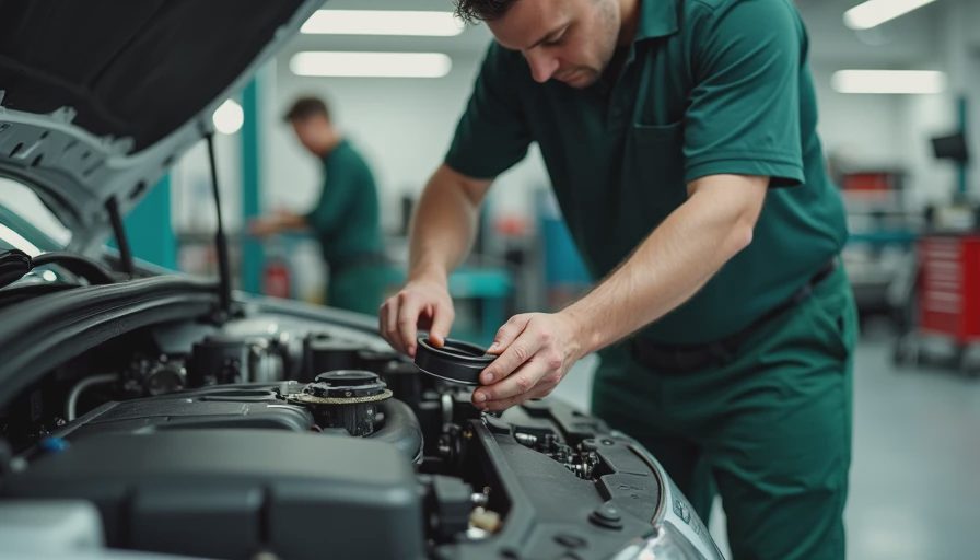
Keep the sealing lip clean and protect it from keyways, splines, threads, and sharp shoulders. A thin plastic sleeve or a wrapped layer of clean tape can prevent the lip from being cut during installation; remove the protection afterward. Lubricate the lip with a compatible operating fluid or assembly lubricant. Do not use an unknown grease simply because it is available at the bench. Thickener chemistry and additives can be incompatible with the elastomer or process fluid.
Install the seal square to the housing bore. A cocked seal creates uneven radial loading, producing a hot spot on one side and a leak channel on the other. Use a driver that contacts the rigid case or the specified installation surface, never the flexible lip. If the design includes a spring, confirm that it has not been displaced during handling. Many seal catalogs provide an installation depth; record that dimension on the work order so the next technician can distinguish a deliberate offset from an error.
Cleanliness deserves the same attention as dimensional accuracy. Wipe the shaft with a lint-free cloth, remove burrs, and inspect the housing bore for corrosion. Do not strike the seal directly with a steel hammer. The impact can deform the case and leave a defect that is invisible until the machine reaches operating speed.
Three Failure Modes, One Root Cause
Leakage at startup may indicate an installation problem, a damaged lip, inadequate initial lubrication, or a shaft that is rotating in the wrong direction for a directional design. Leakage after several operating hours often points toward overheating, incompatible fluid, excessive pressure, or a shaft finish that has polished or cut the lip.
Hard, cracked rubber suggests heat, ozone exposure, or chemical incompatibility. A swollen, soft lip suggests fluid attack or excessive temperature. A narrow polished band can be normal, but a wide shiny track combined with lip wear indicates excessive sliding and insufficient film control. Abrasive particles produce a dull, scored contact surface and may appear as dark paste in the surrounding lubricant.
Pressure is frequently underestimated. A conventional rotary lip seal may handle only limited pressure, while a pressurized gearbox, hydraulic actuator, or compressor requires a design specifically rated for that duty. Verify pressure, speed, temperature, fluid type, and direction of rotation against the manufacturer's data. ISO 6741-1 is relevant to seals used with hydraulic fluids, while ISO 6194 covers rotary-shaft sealing elements; the supplier's design limits remain the final authority for a particular product.
Application Note: In a marine gearbox, saltwater contamination can be more damaging than the initial oil loss. Inspect the outboard side for corrosion and consider whether a separate exclusion lip or protective arrangement is needed. Replacing only the oil-side component can leave the contamination route untouched.
A Practical Selection Checklist
Start with the operating fluid, not the old part number. Record whether the machine uses mineral oil, PAO, ester, glycol-water fluid, grease, or a specialty chemical. Then document shaft diameter, housing diameter, shaft speed, pressure, temperature range, and rotation direction. Note exposure to dust, washdown water, salt spray, abrasive powder, or process vapor.
Select the elastomer for chemical and thermal compatibility, then verify the seal geometry for speed and pressure. Confirm the shaft finish and hardness. For grease-lubricated bearings, ensure the seal can retain the grease without generating excessive friction. NLGI grade identifies grease consistency, not seal compatibility; an NLGI 2 grease can contain very different base oils and additive systems.
Finally, specify the installation method and inspection points before the replacement arrives. A ten-minute measurement of the journal can save several hours of troubleshooting. Keep the failed component in a clean bag and photograph its lip, spring, and contact track. That evidence frequently distinguishes a material failure from misalignment or contamination.
When Replacement Is Not the Real Repair
If the lip seal fails repeatedly, investigate shaft runout, bearing clearance, housing distortion, pressure pulsation, and alignment. A flexible shaft or worn bearing allows the contact to open and close once per revolution. The seal then appears defective even though it is responding to a mechanical problem. Check runout with a dial indicator and compare the result with the equipment and seal manufacturer's limits.
For high-consequence machinery, trend leakage rather than waiting for a puddle. A clean inspection card can record temperature, oil level, vibration, shaft condition, and hours since installation. That simple history helps separate an isolated installation error from a recurring design issue. In my consulting work, the best repair is often not the most expensive seal; it is the one selected after the operating conditions are measured honestly.
A lip seal is inexpensive compared with a gearbox, pump, generator, or production line. Treat it as a tribological component rather than a disposable washer. Match the material to the fluid, provide a suitable shaft surface, install it square and clean, and investigate the system when it fails. Those steps turn a routine replacement into reliable maintenance engineering.


No feedback yet — submit the first.