If you run a CNC shop, a stamping line, or even a small fabrication bay, the metalworking and lubrication process is what stands between a clean part and a scrap bin. In the lab we call this boundary-layer engineering — on your shop floor, it means the difference between a tool that lasts a shift and one that fails at 2 PM on a Friday. That is why getting the fluid, the delivery rate, and the filtering right is not a background detail. It is the production plan.
What Exactly Is the Metalworking and Lubrication Process?
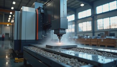
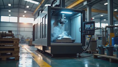
The process is the system that delivers a specially formulated fluid to the interface between a cutting tool and the workpiece. That fluid does four jobs: it cools the cut zone, it flushes away the chip, it reduces friction between the tool face and the newly formed surface, and it protects both the work and the machine from corrosion. Each of those jobs matters, but the priority shifts depending on the operation. Drilling and tapping create a different set of conditions than grinding or broaching. A light mineral oil that works well for gear hobbing will be useless on a surface grinder, where the frictional heat is lower but the surface finish demands a different viscosity.
Any reputable product line follows the ISO 6743-7 classification, which sorts metalworking fluids by their lubricating properties and the type of operation they serve. You will see categories like MIA, MIB, and MHE, and each one expects a specific additive package. When you move from plain water-soluble coolants to neat cutting oils, you are not just changing the carrier — you are changing the whole chemistry.

Three Failure Modes, One Root Cause
In my 25 years of consulting, I keep seeing the same three failure modes on the shop floor: built-up edge on the tool, smeared surfaces on the part, and premature flank wear. The root cause is always the same — the lubricating film is not doing its job. Sometimes the fluid concentration has dropped below the recommended range because nobody is checking the refractometer. Sometimes the fluid is clean but the nozzle is aimed wrong, so the stream never reaches the cut zone. And sometimes the fluid is perfectly fine, but the filter is letting heat and pressure turn the chemistry into sludge.
By the relevant standard, ASTM D2881, a metalworking fluid's performance is tied directly to its viscosity, its extreme-pressure additive content, and the method of application. The standard gives you a framework, but it does not tell you what concentration your specific operation needs. Start with the fluid manufacturer's recommendation, then adjust based on what you actually see in the chip and the tool. In the lab we call this iterative optimization — on your shop floor, it means keeping a log and trusting the wear patterns.
The Physics of the Cut Zone
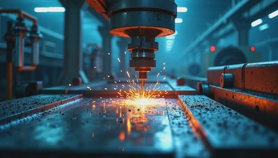
The metalworking and lubrication process is fundamentally a physics problem. At the point where the tool meets the workpiece, pressures routinely exceed 100,000 psi and local temperatures spike above the boiling point of water. The fluid has to get into that gap, survive the heat, and lay down a film that separates the two metal surfaces. There are three lubrication regimes to understand: boundary, mixed, and elastohydrodynamic.
In boundary lubrication, the film is thinner than the surface roughness, so the tool and workpiece are effectively touching. The extreme-pressure additives — usually sulfur, chlorine, or phosphorus compounds — react with the metal surface to form a sacrificial layer. In mixed film, you have a combination of contact and fluid separation. In full film, a continuous layer of fluid keeps the surfaces apart. Most metalworking operations run in the boundary or mixed regimes, which is why the additive chemistry matters more than the base oil viscosity. A cheap oil with the right additives can outperform an expensive oil with the wrong formula.

How to Audit Your Metalworking and Lubrication Process
If you have never audited your fluid program, here is a five-step plan. First, map every machine that uses fluid, including the central system and the individual sumps. Second, use a handheld refractometer to check actual concentration against the label target. A 5% error is enough to explain tool fretting and foam. Third, look at tramp oil and fines floating on top of the sump. Tramp oil can starve the cut zone of oxygen, so remove it with a skimmer or a coalescer. Fourth, monitor pH and microbial growth with a dip slide. When bacteria take hold, the fluid turns acidic and loses its anti-corrosion protection. Fifth, check your filtration micron rating. A grinder might need a 10-micron filter, while a machining center can live with a 40-micron unit.
Application Note: I once worked with a marine parts manufacturer that was replacing drill bits every 400 holes. Their coolant was a straight soluble oil at the wrong concentration, and the sump was full of aluminum fines. After a two-hour audit, we corrected the concentration, added a belt skimmer, and switched to a coarser filter. Within a week, the same drill bit went 1,400 holes. The fix cost less than 300 dollars in hardware.
The Bottom Line for Plant Managers
The metalworking and lubrication process is not a one-time setup. It is a continuous discipline that touches tooling cost, part quality, and operator safety. The fluid is not just a consumable — it is a machine component you can tune. Every time you walk past a sump, ask yourself: what is the concentration, what is the pH, and is the stream hitting the cut zone? The answers will tell you more than any dashboard.
If you are ready to take a hard look at your own operation, start with the audit above. Bring your fluid data sheet and your refractometer. And if you want to go deeper into the chemistry of extreme-pressure additives, leave a comment below. I answer every one, usually with a standard citation and a graph.


No feedback yet — submit the first.