When a hydraulic circuit suffers pressure spikes, slow actuator response, or repeated pump failures, the problem is often energy management rather than oil selection. An accumulator stores hydraulic energy and releases it when the system needs a rapid flow of pressurized fluid. Used correctly, an accumulator reduces pressure pulsation, covers short demand peaks, and gives a pump a less punishing duty cycle. Used incorrectly, it becomes a hidden failure point containing compressed gas and high stored energy.
In the lab we call this energy buffering; on your shop floor, it means steadier motion, fewer emergency stops, and less heat generated across control valves. The first practical rule is simple: identify the accumulator type, confirm its gas charge, and understand what job it is expected to perform before changing settings.
What an accumulator does in a hydraulic circuit
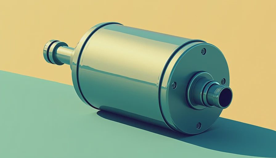
An accumulator stores energy by compressing nitrogen above a hydraulic fluid barrier. Bladder, piston, and diaphragm designs all use this principle, but they behave differently. A bladder accumulator uses an elastomeric bladder to separate nitrogen from oil and responds quickly. A piston accumulator handles larger volumes and can tolerate demanding industrial service, although seal friction and contamination become important. A diaphragm accumulator is compact and often suited to smaller circuits or pulsation control.
The accumulator is not a substitute for an undersized pump. It can supply a short burst of flow, absorb a pressure transient, or maintain pressure while a pump is unloaded. It cannot provide unlimited flow for a continuous high-demand actuator. Sizing therefore begins with the duty cycle: required flow, allowable pressure drop, cycle duration, minimum working pressure, and maximum working pressure.
By the relevant standard, ISO 4413, hydraulic systems should be designed with appropriate safety provisions for stored energy, pressure control, isolation, and discharge. That matters during maintenance. Closing a valve upstream does not automatically make the circuit safe if an accumulator remains charged.
Choosing the right accumulator and volume
Start with the application rather than the catalog number. A molding machine may need rapid injection flow for a few seconds, while a paper-mill tensioning system may need pressure hold during a brief pump transition. A marine steering circuit has different priorities again: response, redundancy, corrosion resistance, and predictable behavior across temperature changes.
For gas-charged service, nitrogen is normally used because it is inert and does not support combustion. Never use compressed air or oxygen. The required gas volume depends on the pressure ratio and the desired oil discharge. In a simplified polytropic model, gas behavior is represented by pV raised to the exponent n as a constant. Slow charging and discharging approach near-isothermal behavior; rapid cycling is closer to adiabatic behavior. That exponent changes the calculated oil volume, so a quick online formula can produce a misleading result when cycle time is short.
A practical sizing review should record precharge pressure, minimum system pressure, maximum system pressure, fluid temperature, cycle frequency, and the required response time. Then compare the calculated volume with the manufacturer’s allowable operating envelope. The accumulator must also have a pressure rating above the system’s maximum possible pressure, including relief-valve behavior and transient spikes.
Application Note: If a hydraulic press becomes slow only during the first few seconds of a cycle, compare pump flow with the accumulator’s usable discharge volume. If speed improves after increasing pump size but motor temperature rises, the original issue may have been peak-flow support rather than total pump capacity.
Precharge is the setting that controls behavior
Precharge is the nitrogen pressure measured with the hydraulic side fully depressurized. It is not the system operating pressure, and it should never be checked by simply reading a gauge while the machine is running. A bladder accumulator with too little precharge can lose response and allow the bladder to collapse against internal hardware. Excessive precharge reduces usable oil volume and can create harsh pressure fluctuations or bladder damage.
The correct value depends on the service. Pulsation dampening, energy storage, and emergency pressure retention each call for different relationships between precharge and minimum system pressure. Follow the accumulator manufacturer’s charging procedure and use a proper nitrogen charging kit with a calibrated gauge. Isolate the unit, bleed hydraulic pressure safely, confirm zero pressure on the fluid side, and then measure or adjust the gas side.
Record the result in the maintenance system. A useful record includes the date, gas pressure, oil-side pressure confirmation, fluid temperature, technician, and reason for adjustment. If an accumulator repeatedly loses precharge, do not keep adding nitrogen without finding the cause. A damaged bladder, leaking gas valve, permeation, or incorrect charging connection may be responsible.
Three accumulator failure modes, one root cause
Three failure modes appear repeatedly in field inspections. First, a bladder can rupture after low precharge allows it to collapse and pinch during cycling. Second, piston seals can wear rapidly when hydraulic fluid is contaminated or the cylinder is misaligned. Third, a gas valve or connection can leak, slowly eliminating the intended energy reserve.
Contamination is the common aggravator. ISO 4406 cleanliness codes provide a standardized way to report particle counts in hydraulic fluid. The right cleanliness target depends on valves, pumps, and servo components, but the principle is universal: particles that seem harmless in a reservoir can damage seals and precision surfaces inside the accumulator and its connected circuit. Use clean transfer equipment, sealed sampling bottles, and filtration suited to the system’s component sensitivity.
Temperature also matters. Gas pressure rises as temperature increases, so a precharge checked in a cold maintenance bay will not match the value observed after hours of operation. Trend readings under comparable conditions. A sudden pressure change, unexplained foaming, nitrogen odor near the valve, or a visible drop in actuator performance deserves investigation before production continues.

Maintenance procedure for safer, longer service
Build accumulator inspection into the preventive maintenance plan rather than waiting for a slow machine. Begin with a visual inspection for corrosion, damaged clamps, loose fittings, oil leakage, and missing identification labels. Confirm the shell rating, inspection interval, and any local pressure-vessel requirements. The nameplate should remain readable; replacing it with an informal label removes important safety information.
Next, review operating pressure and cycle data. Compare current pressure behavior with the original commissioning values. Check that the relief valve, isolation valve, and bleed-down arrangement function as intended. For systems using an accumulator as an emergency reserve, test the actual hold time under controlled conditions instead of assuming stored volume is available.
When fluid sampling is appropriate, pair particle counting under ISO 4406 with viscosity, water, and wear analysis. ASTM D445 is commonly used for kinematic viscosity, while ASTM D6304 can be used for water determination by Karl Fischer titration. These tests do not diagnose every accumulator fault, but they help distinguish fluid degradation from mechanical failure.
Only qualified personnel should remove an accumulator from service. Depressurize both hydraulic and gas sides according to the manufacturer’s instructions, verify isolation, and use lifting equipment for heavy piston units. A pressure vessel that appears empty can still contain dangerous stored energy.
A field checklist for reliable performance
Before commissioning, confirm that the accumulator type matches the duty, the nitrogen charge is documented, the pressure rating exceeds the credible maximum, and the mounting arrangement prevents vibration damage. During operation, watch for pump short cycling, pressure oscillation, unusual heat, sluggish actuators, and alarms that appear only during peak demand. These symptoms often reveal a lost gas charge or inadequate usable volume.
For a production line, schedule a baseline inspection after commissioning and repeat it at a defined interval based on cycle frequency and criticality. Keep spare bladders, seals, charging adapters, and compatible hydraulic fluid available when downtime is expensive. Do not mix elastomer materials without confirming fluid compatibility and temperature limits.
An accumulator is a precise energy-management component, not merely a pressure tank. When its volume, precharge, cleanliness, and safety controls are matched to the machine, it can protect pumps and improve response without creating surprises. Start with measured duty-cycle data, apply ISO 4413 principles, document every gas-pressure check, and treat stored energy with the same respect you give electrical or mechanical energy.





No feedback yet — submit the first.